Beam
It is divided into two parts: check against drawings and check against atlas.
(1) The inspection contents according to the drawings include: reinforcement model, reinforcement diameter, reinforcement quantity, stirrup spacing, and the number of additional stirrups at the junction of primary and secondary beams.
(2) The inspection contents compared with the atlas include: support anchorage length, stirrup densification zone length, waist bar hook arrangement, beam reinforcement length, layout of stirrups on the top layer of coupling beam within the support range, thickness of protective layer, distance from stirrup starting reinforcement to beam edge, opening direction of stirrups on cantilever beam, etc.
Plate
It is divided into two parts: check against drawings and check against atlas.
(1) The inspection contents against the drawings include: reinforcement model, reinforcement diameter, reinforcement quantity, reinforcement spacing and negative reinforcement length of floor slab.
(2) The inspection contents compared with the atlas include: the length of the tight hook of the upper reinforcement (including the anchorage end and end), the thickness of the protective layer, the distance between the starting reinforcement and the support edge, the overlapping length, the anchorage length of the cantilever plate and the anchorage length of the bottom reinforcement, etc.
Drawing Atlas
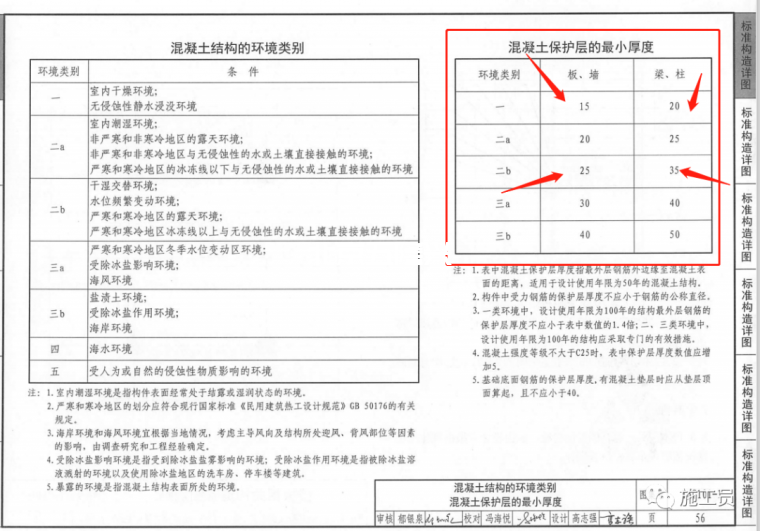
(1) . drawing descriptionFigure 1. Environmental category
Figure 2. Additional stirrups
Figure 3. Length of negative reinforcement of floor slab
Figure IV. partial beam diagram
Figure 5. Concrete strength grade
(2) Atlas method: (16g101 flat method construction drawing and 12g901 irregular reinforcement row are adopted, and the two atlas correspond to each other)


According to the drawing design, grade III earthquake resistance, and the corresponding anchorage length of C30 concrete


According to the drawing design, it is class III seismic, and the corresponding overlapping length of C30 concrete


Practice of coupling beam on the top floor: stirrups may be arranged within the support, with the same diameter as the middle of the span and a spacing of 150mm
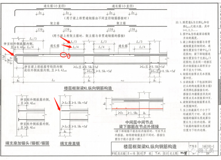
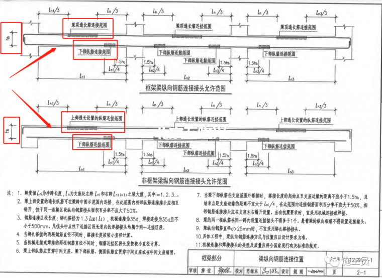
(1) The length of the first row of KL additional reinforcement is 1 / 3ln, and the length of the second row of reinforcement is 1 / 4ln.
(2) When the beam reinforcement is anchored, the hook is not required if the length of the straight anchor is enough, otherwise the hook length is 15d (D is the reinforcement diameter)
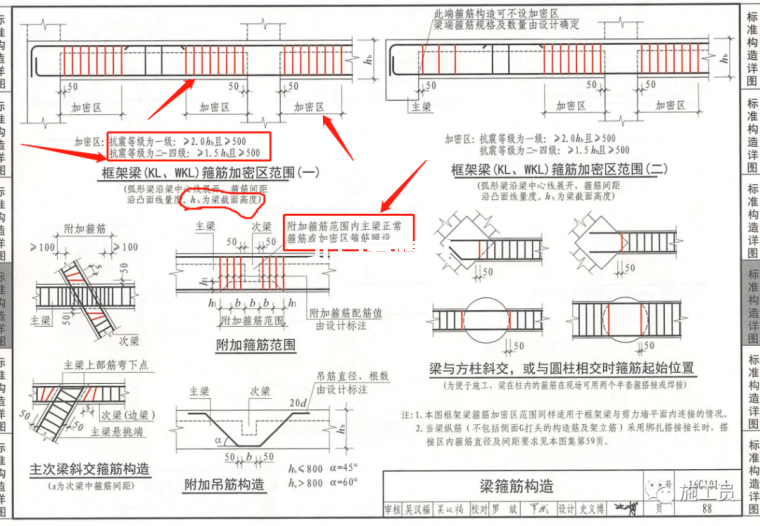
(1) . the length of stirrup densified area of frame beam shall meet two conditions: ≥ 500mm and ≥ 1.5hb and 2.0hb (Hb is the beam height)
(2) . additional stirrups are added at the junction of primary and secondary beams, and the main beam reinforcement is normally arranged
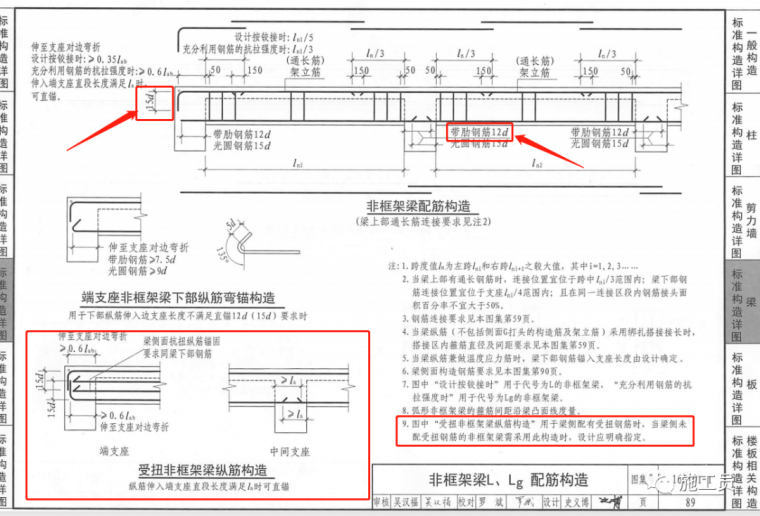
(1) The anchorage of upper reinforcement of non frame beam is the same as KL, and the lower reinforcement is deep into support 12D.
(2) . the longitudinal reinforcement structure of torsion non frame beam needs to be noted in the design.
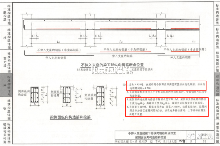
(1) The thickness of beam web HW ≥ 450mm. If there is no mark in the design, the structural reinforcement on the side of the beam also needs to be arranged according to this atlas. (beam web height refers to: beam height minus floor thickness, for example: beam height is 600, floor thickness is 100, and web thickness of this beam is 500)
(2) The side of the beam is reinforced, which is divided into structural reinforcement and torsional reinforcement. The lap length and anchorage length of the two are different.
(3) . the determination of the beam hook is determined by the beam width.
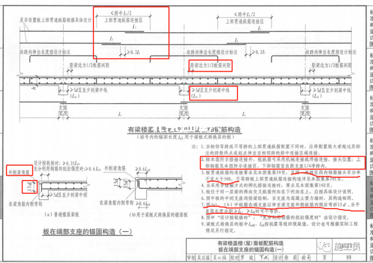
1) The upper reinforcement of the floor slab is overlapped in the middle of the span, and the lower reinforcement is near the support.
(2) . for floor reinforcement, whether the upper or lower reinforcement, the first starting reinforcement is 1 / 2 of the plate reinforcement spacing from the support edge (beam edge).
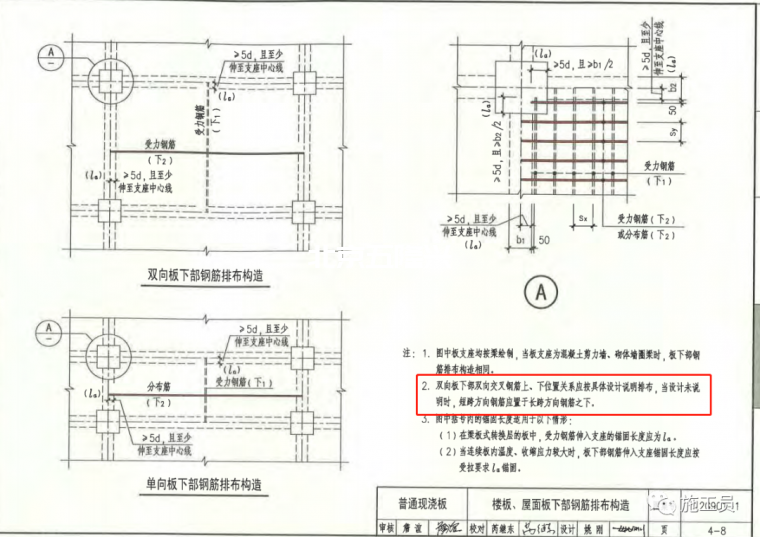
(3) The anchorage of the upper reinforcement of the floor slab at the support is different from that of the lower reinforcement. The upper reinforcement needs to extend to the inner side of the corner reinforcement outside the beam and the hook length is 15d (when the length of the horizontal section is greater than the anchorage length, it can not be hooked), and the lower reinforcement is ≥ 5D and passes through the beam.
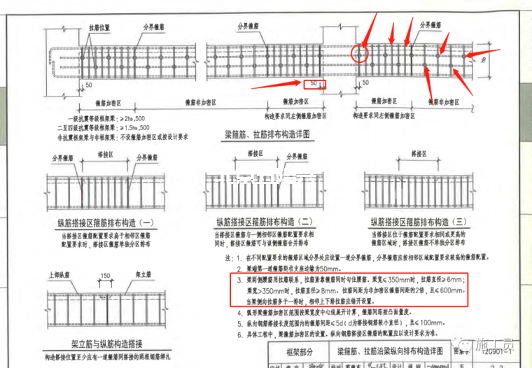
(1) The first stirrup at the beam end is 50mm from the edge of the support.
(2) The pull hook in the beam is close to the stirrup and hooks the waist reinforcement at the same time.
(3) When there are more than two rows of waist bars, the pull hooks shall be staggered.
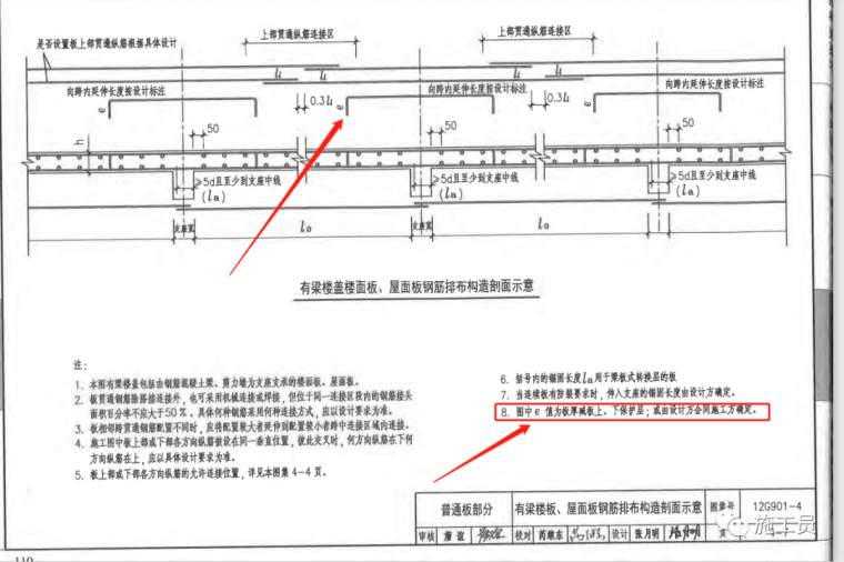
In general, the reinforcement in the short span direction shall be placed under the long reinforcement.
The thickness of the protective layer shall be determined according to the environmental category of the drawing design
 五隆興科技發(fā)展有限公司


